Tarjetas multifuncionales PCIe
Características del producto
PCI Express is the latest implementation of the PCI bus, which is only software-compatible with other PCI bus specifications. The PCI Express hardware layout is totally different (it is not possible to install a PCI Express card in a PCI/PCI-X slot or vice-versa).
Meinberg offers PCIe timing devices for computer and network synchronization in both low-profile and regular sizes.
Models:
– GPS180PEX
Low Profile GPS Clock (PCI Express)
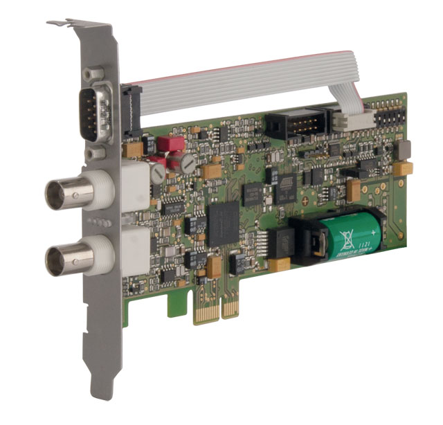
The board GPS180PEX is designed as a low profile board for computers with PCI Express interface. The rear slot cover integrates the antenna connector, a BNC connector for modulated time codes, a 9pin D_SUB male connector and two status LEDs. With this standard height bracket you can use the D_SUB connector for I/O signals like RS-232 – PPS and PPM and you can use this interface for firmware updates.
The GPS180PEX will be delivered with a low profile bracket. You can mount this part instead of the standard bracket, to run the GPS180PEX in computers with smaller housing (e.g. 1U server).
– PEX511
DCF77 Computer Clock (PCI Express)
DCF77 radio clock for synchronization of computers and networks in PCIe form factor, can be used in both low profile and regular PCIe slots.
Notice: End-of-Life Status announced. This product is only available in a small number of pieces. It is going to be replaced by the highly accurate PZF180PEX, which provides many new features. The PZF180PEX can already be ordered.
– PTP270PEX
IEEE1588-2008 slot card for computers (PCI Express)
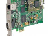
The PTP270PEX provides sub-microsecond accuracy for computers. The card has been designed to add ultra precise time stamping capabilities to your data acquisition and measurement applications. The PCI Express card can be installed in any single lane PCIe slot and offers an impressive selection of time, pulse and frequency outputs.
– TCR511PEX
IRIG Time Code Receiver for Computers (PCI Express)
Reception of IRIG-A/B or AFNOR time codes for synchronization of computers and networks in PCI Express form factor, can be used in both low profile and regular PCIe slots.
– TCR170PEX
IRIG Time Code Receiver and Generator for Computers (PCI Express)
The TCR170PEX receives IRIG-A/B or AFNOR time codes and can be used for synchronizing the system time of its host PC. The IRIG output of this card can generate an IRIG signal for other IRIG time code readers. The output format is independent from the incoming IRIG signal – a perfect solution to your IRIG conversion requirements.
– PZF180PEX
Low Profile DCF77 Clock (PCI Express)
The board PZF180PEX is designed as a low profile board for computers with PCI Express interface. The rear slot cover integrates the antenna connector, a BNC connector for modulated time codes, a 9pin D_SUB male connector and two status LEDs. With this standard height bracket you can use the D_SUB connector for I/O signals like RS-232 – PPS and PPM and you can use this interface for firmware updates.
The PZF180PEX will be delivered with a low profile bracket. You can mount this part instead of the standard bracket, to run the PZF180PEX in computers with smaller housing (e.g. 1U server).
Especificaciones técnicas
| MODEL | GPS180PEX |
| Type of receiver | 12 channel GPS C/A-code receiver |
| Type of antenna | Remote powered GPS antenna/converter unit, up to 300m distance to antenna with RG58 and up to 700m distance with RG213 cable |
| Status info | Fail-LED shows that the internal timing has not been synchronized or that a system error occurred |
| Lock-LED shows that the calculation of the position has been achieved after reset | |
| Synchronization time | Max. 1 minute in normal operation mode, approx. 12 minutes after a cold start (discharged buffer battery) |
| Frequency outputs | Frequency output 10 MHz, TTL level |
| Pulse outputs | 3 Programmable TTL outputs, per default configured as: |
| Channel 0: Pulse per second (TTL, RS232 level), pulse duration: 200 msec | |
| Channel 1: Pulse per minute (TTL), pulse duration: 200 msec | |
| Channel 2: DCF77 compatible pulses (TTL level), pulse width: 100/200 msec | |
| Accuracy of pulse outputs | Depends on oscillator option: |
| < ±250ns (TCXO, OCXO LQ) | |
| < ±100ns (OCXO MQ, OCXO HQ, OCXO DHQ) | |
| Standard: TCXO | |
| Interface | Single serial RS232 interface |
| Data format PC interface | Binary, byte serial |
| (compatible with Meinberg DCF77 Slot Card PEX511) | |
| Data format of interfaces | Baudrate: 300, 600, 1200, 2400, 4800, 9600, 19200 Baud |
| Data format: 7N2, 7E1, 7E2, 8E1, 8N1, 8N2 | |
| Time telegram: Meinberg Standard-Telegram, SAT, Uni Erlangen (NTP), SPA, NMEA0183 (RMC) or capture-telegramm | |
| Statusbyte | Informations about free running mode, daylight savings time and DST pre-switch anouncement, synchronization since last reset, GMT/UTC time and validity of the hardware clock data |
| Unmodulated time code output | DCLS, TTL into 50 ohm (active high or active low) |
| Modulated time code output | IRIG AM sine wave signal: |
| 3Vpp (MARK), 1Vpp (SPACE) into 50 ohm | |
| Generated time codes | IRIG B002: 100pps, DCLS signal, no carrier, BCD time of year |
| IRIG B122: 100pps, AM sine wave signal, 1 kHz carrier, BCD time of year | |
| IRIG B003: 100pps, DCLS signal, no carrier, BCD time of year, SBS time of day | |
| IRIG B123: 100pps, AM sine wave signal, 1kHz carrier, BCD time of year, SBS time of day | |
| IRIG B006: 100 pps, DCLS Signal, no carrier, BCD time-of-year, Year | |
| IRIG B126: 100 pps, AM sine wave signal, 1 kHz carrier frequency, BCD time-of-year, Year | |
| IRIG B007: 100 pps, DCLS Signal, no carrier, BCD time-of-year, Year, SBS time-of-day | |
| IRIG B127: 100 pps, AM sine wave signal, 1 kHz carrier frequency, BCD time-of-year, Year, SBS time-of-day | |
| IEEE1344: Code according to IEEE1344-1995, 100pps, AM sine wave signal, 1kHz carrier, BCD time of year, SBS time of day, IEEE1344 expansion for date, time zone, daylight saving and leap second in Control Funktions Segment | |
| C37.118: Like IEEE1344 – with turned sign bit for UTC-Offset | |
| AFNOR: Code according to NFS-87500, 100pps, AM sine wave signal, 1kHz carrier, BCD time of year, complete date, SBS time of day | |
| Time-Trigger inputs | Resolution: 100 nsec, triggered by falling TTL slope |
| Time of trigger event readable via computer slot or optional second RS232-interface | |
| Electrical connectors | BNC female connector for antenna |
| BNC female connector for modulated timecode | |
| 9 pin sub D male connector | |
| Computer interface | Single lane (x1) PCI Express (PCIe) Interface |
| PCI Express r1.0a compatible | |
| Backup battery type | When main power supply fails, hardware clock runs free on quartz basis, almanac data is stored in RAM |
| Life time of lithium battery min. 10 years | |
| Board type | Low Profile card (68,90 x 150 mm) |
| Ambient temperature | 0 … 50°C / 32 … 122°F |
| Humidity | Max. 85% |
| Options | Oscillator upgrade: |
| OCXO-LQ, -MQ or -HQ (instead of TCXO) for extended Holdover capabilities | |
| (see oscillator table for further details) | |
| RoHS-Status of the product | This product is fully RoHS compliant |
| WEEE status of the product | This product is handled as a B2B category product. In order to secure a WEEE compliant waste disposal it has to be returned to the manufacturer. Any transportation expenses for returning this product (at its end of life) have to be incurred by the end user, whereas Meinberg will bear the costs for the waste disposal itself. |
| MODEL | PEX511 |
| Type of receiver | Narrowband DCF77 quadrature receiver with automatic gain control, bandwidth: approx. 20Hz |
| Status info | RF Signal: Indicated by LED, antenna alignment enhanced by utility program |
| Free running: Indicated by LED and utility program, without RF signal the clock runs on quartz basis | |
| Modulation: Indicated by LED and utility program | |
| Reception Control | Multiple check of received time telegram |
| Plausibility control by using two complete time telegrams | |
| Pulse outputs | Pulses per second (RS232/TTL level) and per minute (TTL level), pulse duration: 100 msec, active high |
| (only available with “standard height” bracket or with additional “low profile” bracket). | |
| Interface | One serial RS232 interface |
| (only available with “standard height” bracket or with additional “low profile” bracket). | |
| Data format PC interface | Binary, byte serial |
| Data format of interfaces | Baudrate: 300, 600, 1200, 2400, 4800, 9600 baud |
| Framing: 7E2, 8N1, 8E1, 8N2 | |
| Output string: 32 ASCII characters with date, time and status information | |
| Statusbyte | Informations about free running mode, daylight savings time and DST pre-switch anouncement, synchronization since last reset, GMT/UTC time and validity of the hardware clock data |
| Electrical connectors | BNC female connector |
| 9 pin sub D male connector (only available with “standard height” bracket or with additional “low profile” bracket) | |
| Computer interface | Single lane (x1) PCI Express (PCIe) Interface |
| PCI Express r1.0a compatible | |
| Backup battery type | In case of supply voltage failure the on-board RTC keeps the time based on XTAL for more than 150 hours (buffer capacitor) |
| Optional: lithium backup battery (life time: 10 years) | |
| Board type | Low profile board (68,90 x 150 mm) |
| Ambient temperature | 0 … 50°C / 32 … 122°F |
| Humidity | Max. 85% |
| Scope of supply | Scope of supply includes: |
| – an active ferrite antenna AI01 and 5m of RG174 coaxial cable with BNC connectors. | |
| Optional: AW02 with RG58 and patch cord, other length of cable | |
| – “low profile” bracket | |
| RoHS-Status of the product | This product is fully RoHS compliant |
| WEEE status of the product | This product is handled as a B2B category product. In order to secure a WEEE compliant waste disposal it has to be returned to the manufacturer. Any transportation expenses for returning this product (at its end of life) have to be incurred by the end user, whereas Meinberg will bear the costs for the waste disposal itself. |
| MODEL | PTP270PEX |
| Accuracy | +-20 ns to grandmaster clock |
| Status info | 4 Status LEDs: |
| System Status | |
| Outputs active | |
| PTP packet sent | |
| PTP packet received | |
| Frequency outputs | Frequency output 10 MHz, TTL level |
| Pulse outputs | Pulse Per Second (PPS), TTL level, pulse width: 200ms |
| Accuracy of pulse outputs | +/- 100 ns (relative to the used IEEE 1588 Grandmaster Clock, after initial synchronization phase) |
| Interface | Single serial RS232 interface |
| Unmodulated time code output | DCLS, TTL into 50 ohm (active high or active low) |
| Generated time codes | |
| B002: 100pps, DCLS signal, no carrier, BCD time of year | |
| B003: 100pps, DCLS signal, no carrier, BCD time of year, SBS time of day | |
| IEEE1344: Code according to IEEE1344-1995, 100pps, BCD time of year, SBS time of day, IEEE1344 expansion for date, time zone, daylight saving and leap second in Control Functions segment (CF) | |
| AFNOR: Code according to NFS-87500, 100pps, BCD time of year, complete date, SBS time of day | |
| Time-Trigger inputs | Resolution: 20 nsec, triggered by falling TTL slope |
| Time of trigger event readable via PCI Express interface | |
| Computer interface | Single lane (x1) PCI Express (PCIe) Interface |
| PCI Express r1.0a compatible | |
| Network Interface | 1 x 10/100 MBit with RJ45, IEEE 1588 |
| Power supply | +3.3V, @ 600mA |
| +12V, @ 300mA | |
| Board type | Standard height board (101 x 150 mm) |
| Precision Time Protocol (IEEE 1588) | PTP/ IEEE 1588-2008 Multicast including |
| Network Protocols: | |
| – UDP/IPv4 (Layer 3) | |
| – IEEE 802.3 (Layer 2) | |
| Delay Mechanisms: | |
| – End-to-End | |
| – Peer-to-Peer | |
| PTP Management Messages for monitoring and configuration | |
| Ambient temperature | 0 … 50°C / 32 … 122°F |
| Humidity | Max. 85% |
| Options | Oscillator upgrade: |
| OCXO-LQ, -MQ or -HQ (instead of TCXO) for extended Holdover capabilities | |
| (see oscillator table for further details) | |
| RoHS-Status of the product | This product is fully RoHS compliant |
| WEEE status of the product | This product is handled as a B2B category product. In order to secure a WEEE compliant waste disposal it has to be returned to the manufacturer. Any transportation expenses for returning this product (at its end of life) have to be incurred by the end user, whereas Meinberg will bear the costs for the waste disposal itself. |
| MODEL | TCR511PEX |
| Status info | 3 status LEDs for indication of: detection of a correct code, synchronization of the internal timing and holdover mode |
| Input signal | Modulated IRIG A/B or AFNOR signal, input insulated by transformer, input impedance selectable by jumper: 50, 600 or 5000 ohm |
| unmodulated (DC level shift) IRIG A/B or AFNOR signal, input insulated by photocoupler | |
| (DC level shift only available with “standard height” bracket or with additional “low profile” bracket). | |
| Accuracy free run | ±1·10E-6 if the decoder was synchronous for at least 1 h |
| IRIG Time Code Input | IRIG-A133, A132, A003, A002, B123, B122, B003, B002 and AFNOR NFS 87-500 (other codes on request) |
| Pulse outputs | Pulses per second (RS232/TTL level) and per minute (TTL level), pulse duration: 200 msec, active high |
| (only available with “standard height” bracket or with additional “low profile” bracket). | |
| Precision of timebase | ±5 µsec referred to IRIG-reference marker |
| Interface | One serial RS232 interface |
| (only available with “standard height” bracket or with additional “low profile” bracket). | |
| Data format PC interface | Binary, byte serial |
| Data format of interfaces | Baudrate: 300, 600, 1200, 2400, 4800, 9600, 19200, 38400 baud |
| Framing: 7E2, 8N1, 8E1, 8N2 | |
| Output string: 32 ASCII characters with date, time and status information | |
| Statusbyte | Information about holdover mode, synchronization since last reset and the validity of the RTC data. |
| Electrical connectors | BNC female connector |
| 9 pin sub D male connector (only available with “standard height” bracket or with additional “low profile” bracket) | |
| Computer interface | Single lane (x1) PCI Express (PCIe) Interface |
| PCI Express r1.0a compatible | |
| Backup battery type | When main power supply fails, hardware clock runs free on quartz basis, life time of lithium battery min. 10 years |
| Board type | Low profile board (68,90 x 150 mm) |
| Ambient temperature | 0 … 50°C / 32 … 122°F |
| Humidity | Max. 85% |
| RoHS-Status of the product | This product is fully RoHS compliant |
| WEEE status of the product | This product is handled as a B2B category product. In order to secure a WEEE compliant waste disposal it has to be returned to the manufacturer. Any transportation expenses for returning this product (at its end of life) have to be incurred by the end user, whereas Meinberg will bear the costs for the waste disposal itself. |
| MODEL | TCR170PEX |
| Status info | 2 status LEDs for indication of: detection of a correct code, synchronization of the internal timing and holdover mode |
| Input signal | Modulated IRIG A/B, IEEE1344 or AFNOR signal, input insulated by transformer, input impedance 50 ohm, 600 ohm or 5 kohm selectable by jumper |
| unmodulated (DC level shift) IRIG A/B, IEEE1344 or AFNOR signal, input insulated by photocoupler | |
| Accuracy free run | ±1·10E-8 if the decoder was synchronous for at least 1 h |
| IRIG Time Code Input | IRIG-A133, A132, A003, A002, B123, B122, B003, B002, IEEE1344 and AFNOR NFS 87-500 (other codes on request) |
| Frequency outputs | Frequency synthesizer 1/8 Hz up to 10 MHz (TTL, sine 1,5Vrms) |
| Pulse outputs | Three programmable pulse outputs, TTL level |
| Channel 0 also with RS232 level | |
| Precision of timebase | ±5 µsec referred to IRIG-reference marker |
| Interface | Two independant serial RS232 interfaces |
| Data format PC interface | Binary, byte serial |
| Data format of interfaces | Baudrate: 300, 600, 1200, 2400, 4800, 9600, 19200, 38400 baud |
| Framing: 7E2, 8N1, 8E1, 8N2 | |
| Output string: 32 ASCII characters with date, time and status information | |
| Statusbyte | Information about holdover mode, synchronization since last reset and the validity of the RTC data. |
| Generated time codes | IRIG-B123, B122, B003, B002, IEEE1344 and AFNOR NFS 87-500 (other codes on request) |
| Output signal | Modulated IRIG-B or AFNOR signal, 3 Vpp (high) and 1 Vpp (low) into 50 ohm |
| unmodulated (DC Level Shift) IRIG-B or AFNOR signal, TTL into 50 ohm and RS-422, active high or active low selectable by jumper | |
| Time-Trigger inputs | Triggered by falling TTL slope |
| Time of trigger event readable via computer slot or optional second RS232-interface | |
| Electrical connectors | Female BNC-connectors |
| male 9-pole D-Sub connector | |
| Computer interface | Single lane (x1) PCI Express (PCIe) Interface |
| PCI Express r1.0a compatible | |
| Backup battery type | When main power supply fails, hardware clock runs free on quartz basis, life time of lithium battery min. 10 years |
| Board type | Standard height board (101 x 150 mm) |
| Ambient temperature | 0 … 50°C / 32 … 122°F |
| Humidity | Max. 85% |
| Options | – Optical input and/or output for time codes, ST connector for GI 50/125µm or GI 62,5/125µm gradient fibre |
| – OCXO LQ/MQ/HQ (specifications look at oscillator options) for higher accuracy in holdover mode | |
| RoHS-Status of the product | This product is fully RoHS compliant |
| WEEE status of the product | This product is handled as a B2B category product. In order to secure a WEEE compliant waste disposal it has to be returned to the manufacturer. Any transportation expenses for returning this product (at its end of life) have to be incurred by the end user, whereas Meinberg will bear the costs for the waste disposal itself. |
| MODEL | PZF180PEX |
| Type of receiver | Quadrature receiver for optimized evaluation of the DCF signals (amplitude and phase modulation) |
| Type of antenna | DCF77 outdoor antenna AW02 |
| Status info | The Field-LED is switched on if a DCF-signal with at least minimum field strength needed for the correlation receiption is detected at the input of the receiver. Whenever the reception of the pseudorandom PZF signal is not possible but the AM signal is available, the ‘Field’-LED starts to blink once per second with a pulse duration of 100 or 200ms, corresponding to the demodulated DCF pulses. |
| Synchronization | Compared to the former PZF computer clock the PZF180PEX not just provides the capability to evaluate the common amplitude modulated AM signal it is also able to decode the high-precision pseudorandom phase noise. If the PZF signal is disturbed an cannot be received, the PZF180PEX automatically switches over to decode the AM signal, if available, and ensures synchronization. |
| Frequency outputs | Frequency output 10 MHz, TTL level |
| Pulse outputs | 3 Programmable TTL outputs, per default configured as: |
| Channel 0: Pulse per second (TTL, RS232 level), pulse duration: 200 msec | |
| Channel 1: Pulse per minute (TTL), pulse duration: 200 msec | |
| Channel 2: DCF77 compatible pulses (TTL level), pulse width: 100/200 msec | |
| Accuracy of pulse outputs | Better than +/- 50μsec after synchronization and 20 minutes of operation. |
| Interface | Single serial RS232 interface |
| Data format PC interface | Binary, byte serial |
| (compatible with Meinberg DCF77 Slot Card PEX511) | |
| Data format of interfaces | Baudrate: 300, 600, 1200, 2400, 4800, 9600, 19200 Baud |
| Data format: 7N2, 7E1, 7E2, 8E1, 8N1, 8N2 | |
| Time telegram: Meinberg Standard-Telegram, SAT, Uni Erlangen (NTP), SPA, NMEA0183 (RMC) or capture-telegramm | |
| Unmodulated time code output | DCLS, TTL into 50 ohm (active high or active low) |
| Modulated time code output | IRIG AM sine wave signal: |
| 3Vpp (MARK), 1Vpp (SPACE) into 50 ohm | |
| Generated time codes | IRIG B002: 100pps, DCLS signal, no carrier, BCD time of year |
| IRIG B122: 100pps, AM sine wave signal, 1 kHz carrier, BCD time of year | |
| IRIG B003: 100pps, DCLS signal, no carrier, BCD time of year, SBS time of day | |
| IRIG B123: 100pps, AM sine wave signal, 1kHz carrier, BCD time of year, SBS time of day | |
| IRIG B006: 100 pps, DCLS Signal, no carrier, BCD time-of-year, Year | |
| IRIG B126: 100 pps, AM sine wave signal, 1 kHz carrier frequency, BCD time-of-year, Year | |
| IRIG B007: 100 pps, DCLS Signal, no carrier, BCD time-of-year, Year, SBS time-of-day | |
| IRIG B127: 100 pps, AM sine wave signal, 1 kHz carrier frequency, BCD time-of-year, Year, SBS time-of-day | |
| IEEE1344: Code according to IEEE1344-1995, 100pps, AM sine wave signal, 1kHz carrier, BCD time of year, SBS time of day, IEEE1344 expansion for date, time zone, daylight saving and leap second in Control Funktions Segment | |
| C37.118: Like IEEE1344 – with turned sign bit for UTC-Offset | |
| AFNOR: Code according to NFS-87500, 100pps, AM sine wave signal, 1kHz carrier, BCD time of year, complete date, SBS time of day | |
| Time-Trigger inputs | Resolution: 100 nsec, triggered by falling TTL slope |
| Time of trigger event readable via computer slot or optional second RS232-interface | |
| Electrical connectors | BNC female connector for antenna |
| BNC female connector for modulated timecode | |
| 9 pin sub D male connector | |
| Computer interface | Single lane (x1) PCI Express (PCIe) Interface |
| PCI Express r1.0a compatible | |
| Backup battery type | In case of supply voltage failure the on-board RTC keeps the time based on XTAL for more than 150 hours (buffer capacitor) |
| Optional: lithium backup battery (life time: 10 years) | |
| Board type | Low Profile card (68,90 x 150 mm) |
| Ambient temperature | 0 … 50°C / 32 … 122°F |
| Humidity | Max. 85% |
| Scope of supply | Scope of supply includes: |
| – an active ferrite antenna AI01 and 5m of RG174 coaxial cable with BNC connectors. | |
| Optional: AW02 with RG58 and patch cord, other length of cable | |
| – “low profile” bracket | |
| Options | Oscillator upgrade: OCXO-LQ, -MQ or -HQ (instead of TCXO) for extended Holdover capabilities |
| RoHS-Status of the product | This product is fully RoHS compliant |
| WEEE status of the product | This product is handled as a B2B category product. In order to secure a WEEE compliant waste disposal it has to be returned to the manufacturer. Any transportation expenses for returning this product (at its end of life) have to be incurred by the end user, whereas Meinberg will bear the costs for the waste disposal itself. |